MEASURE RESONANCE OF ANTENNA TRAPS
INTRODUCTION
 |
Measuring antenna traps is often by using a (grid)dipmeter, but that only works well if the trap is not enclosed in a metal casing.
This requires a different measuring method and various systems are shown on the internet.
After testing those measuring methods, they were not my choice and the following system is the result of more experimentation.
MEASURING METHOD
The trap to be measured is loaded with 3 kOhm (2 × 1k5 in series).
With end-fed antennas, the "resistance" to fed the high-impedance antenna is approximately 2450 Ohm and, to be on the safe side, 3 kohm has been chosen as the load
for the high-impedance trap.
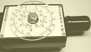
A signal generator is required for the measurement, but if this is not available, an existing transceiver can be used as a signal generator.
In the diagram you can see how the reduced transmission signal of the set uses a capacitive attenuator and an 50 Ohm artificial load to provide a suitable measuring signal.
The output voltage of the trap is measured with an oscilloscope (CRO) or meter. The last after the signal has been rectified with the circuit shown.
A trap is a parallel circuit with a high impedance, so for resonance a minimum signal must be found on a scope or meter.
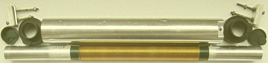
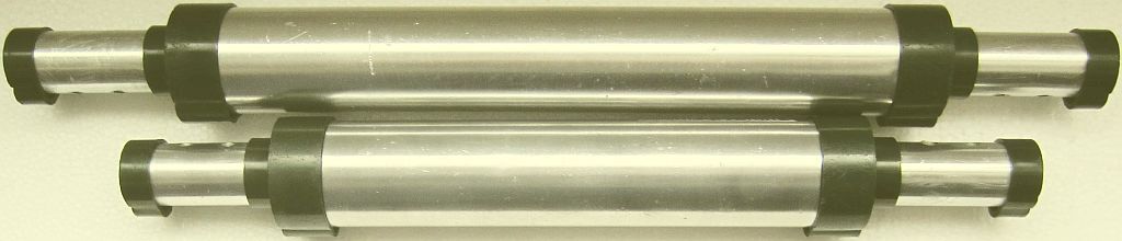
CONNECT TRAP CORRECTLY
For a trap with a metal tube, the envelope is the parallel capacitance of the system. One side of the tube is connected to the an and of the coil. The other side is an open end which
functions equal to an antenna stub. This is the correct input to inject the driving signal.
Install an antenna trap so that the open end points towards the feedpoint.
![]()
